Designing an optimal oversized array
‘Array oversizing’ refers to solar photovoltaic panel systems that have been designed so that the solar array has a higher peak capacity than the inverter.
A solar system of a given installed capacity under irradiance consistent with Standard Test Conditions may actually deliver up to 20 per cent less than the nameplate rating of the solar array.
This is because of the system’s and solar modules’ losses.
Oversizing the solar array has the potential to increase the system yield as it results in a higher PV array power output during times of low irradiance (e.g. the morning and evening, and cloudy days).
The recent trend of reduced costs of PV modules compared to the cost of inverters has introduced the concept of oversizing the PV array as a cost-effective method for increasing system output. The metric used to measure oversizing is known as the DC-AC ratio, array-to-inverter ratio, or simply the oversizing-ratio. For example a 3kW inverter with an oversizing ratio of '2' will use a 6kWp array.
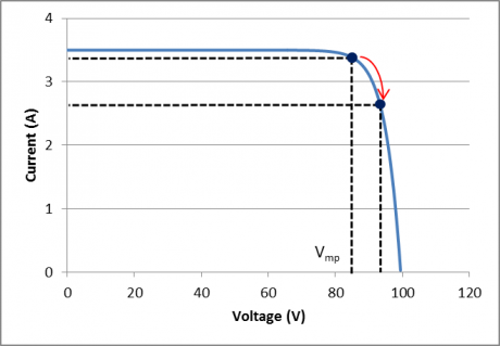
In order to connect an inverter with an oversized array, it is important to understand how the inverter limits the input DC current. For an inverter to be suitable for use with an oversized array, it must be capable of limiting the current flowing from the array. This means the inverter will function as follows:
Figure 1: IV curve showing different operating voltages for the array. If the inverter is suitable for oversizing it will increase the operating voltage of the array; reducing the current. This will cause a net decrease in array power.
Before designing an oversized array, assurance, preferably in writing, must be gained from the inverter manufacturer that their equipment is suitable for this application, and the inverter’s use in this way will not void the warranty.
Many inverter data sheets also list a maximum DC power. Clarification is required from the manufacturer if this figure is a safety restriction on the inverter, or simply the maximum amount of DC power that can be converted to AC. It is essential that confirmation be sought from the inverter’s manufacturer that their product is suitable for use with an oversized array and that the manufacturer’s warranty will be honoured.
Each inverter technology is different and may be affected differently when connected to an oversized array. In such a situation (and assuming the inverter is capable of restricting its input current) the inverter will be operating at its maximum power capacity for a larger proportion of the time. This means that components within the inverter will also be operating at their maximum capacity for longer, which may be significant if the inverter design and selection of components assumed a smaller array size. There is a risk that individual components will age faster than anticipated due to higher components’ operating temperatures, and cause the inverter to fail earlier than expected.
To minimise this potential adverse effect, it is even more important that the inverter be installed in shade or a suitable cool environment. Inverters may be equipped with temperature sensors that can shut down the equipment in the event of overheating or regulate the operation of internal cooling fan/s in response to temperature variations. These are important aspects to consider when selecting an inverter for an oversized array. It is also important to note that the current Clean Energy Council design guidelines do not allow the inverter to be undersized by more than 75 per cent in relation to the array. Expressed in another way, under these guidelines, the array cannot be oversized by more than 133 per cent of the inverter AC capacity.
By oversizing the array, the inverter is operated at its maximum capacity for a larger percentage of time. PV modules are rated at Standard Test Conditions: at an operating temperature of 25 degrees, and irradiance of 1000W/m2. In reality, modules operate at around 65 degrees and at irradiances well below 1000W/m2 (either due to bad weather or time of day). This means that an array will rarely be operating at its Watt-peak (Wp) capacity.
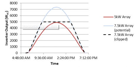
By oversizing the array the system will produce more power in the morning and evening, and during other times of low solar irradiation. In effect this will increase the amount of time that inverters are operating at their nameplate capacity. The downside of oversizing is that when solar conditions are favourable, the output of the array is ‘clipped’ and potential energy from the system is lost (Figure 2).
Figure 2: Clipping effect when a 5kW inverter is connected to oversized array (7.5kW; i.e. a 150 per cent oversizing ratio). The area above the 5kW line represents energy that is wasted.
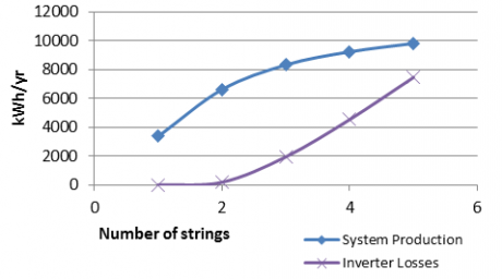
Basic modelling indicates that the maximum benefit of oversizing is realised with an oversizing ratio of 150 per cent. This modelling was based on a 5kW inverter, being fed with strings each rated at 2.4kW. With two strings, the system represented an oversizing ratio of 96 per cent (an array power of 4.8kW). These results are displayed below in Figure 3.
Figure 3: Sample system production and losses of a system with 5kW inverter and 2.4kW strings. In this modelling two strings represent an array that is closely matched to the inverter (4.8kW)
Beyond a sizing coefficient of 150 per cent, the losses from any additional strings will be greater than the incremental gain in production (Figure 4). This is because for most of the day the array has the potential to produce more current than the inverter can handle. The inverter’s specifications should state what the maximum DC power input rating is for the inverter; if stated this figure should not be exceeded (see above). It is only during overcast and low light conditions that the additional current is useful. In effect this lowers the efficiency of each additional string, as the inverter will increase the operating voltage of the array above Vmp in an effort to reduce the array current.
Figure 4: Additional gains and losses of a 5kW system.
The cost benefit analysis of oversizing is a function of how much of the system cost is due to the array (both in materials and labour), and how much is due to the inverter and other BOS costs.
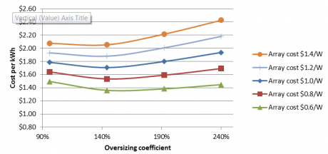
Figure 5 shows the results of modelling various costs of the above system; assuming a static cost of $1.60/W for the inverter and BOS, and array costs varying between $1.40/W and $0.60/W. As can be seen for all costs within this range, the optimal cost-benefit point is also at a sizing of around 150 per cent. These assumptions are optimistic however as although module prices are predicted to drop further, there could also be price reductions in the inverter and BOS costs as the industry matures. Installation labour costs of the system will also increase with the scale of oversizing. The financial benefit from oversizing relies on the solar array being much cheaper than other components of the system.
Figure 5: Cost of generation over single year assuming various array costs. Inverter and BOS costs are assumed constant at $1.60/W installation costs.
Jono Pye is an engineer at Global Sustainable Energy Solutions.


